Constructing flat patterns for clothing has always been challenging long before the age of computers. Yet, even as the world of digital tools began to take over field after field of design and construction, the model makers somehow only got a handful of software packages, inheriting their nature from CAD environments that weren't meant for clothing patterns. Users were forced to put almost greater effort in mastering the software than creating their garments.
After many years of highly dedicated development we are very proud and excited to present to you White Rabbit CAD. Key to what makes it so special is its directness and simplicity, which comes from our philosophy to bring the sensation of working on paper into the digital age.
While creating clothing patterns is very much engineering work, it is an art form. As such it requires both the ability to focus on the technical aspects of pattern construction as well as on artistic intentions regarding the design.
To us it has been of the utmost importance to make the software as intuitve and simple as possible so that it itself won't absorb your attention and you may concentrate on your ideas instead.
In order to achieve this goal, we've had to develop a highly elaborate system beneath the surface, which understands how to connect actions and interactions between tools and parameters allowing you to create and modify them freely and naturally without having to do much of any preparation or abstract predefinitions.
We are convinced that there is literally no easier way of constructing flat patterns from scratch than with White Rabbit CAD, but even now we believe we are only at the beginning, looking at all the additonal ideas we have accumulated over the years of its development and all that keep coming to us.
In all cases we recommend the use of a mouse with a mouse wheel. We are preparing versions for touch use, but even then it's truly more pleasant to work with a mouse.
Windows:
Windows 7 (64 bit) or higher (Windows 8.1, Windows 10)
Installation on macOS: double click the downloaded "whiterabbitcad.dmg" to open the image window, where you simply drag the WhiteRabbitCAD icon unto the Application folder icon.
Every application downloaded from the internet may still require your approval to be installed.
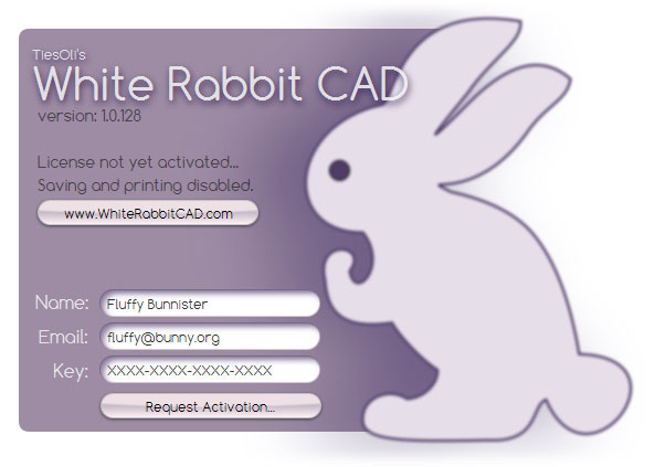
When starting the software for the first time, the splash screen will greet you with the Activation Procedure.
You will have to be connected to the internet in order to validate your copy of White Rabbit CAD.
You will have to enter your Name, the Email address you've chosen for your subscription and the Activation Key. You may have already received an email with the key and your order id at that email address. Once all was entered properly, the "Request Activation..." button will be enabled and you may press it to validate your license.
After this you will be able to start your journey with White Rabbit CAD.
White Rabbit CAD comes with a solid user interface, rather than floating windows. It's designed to provide consistency, clarity and focus for each part of the pattern creation process.
Features are not hidden inside layers of submenus, but rather present themselves openly for each major task section. Those sections are designed for the sake of clarity and you may switch between all of them at any time. More details are coming next...
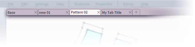
Pattern Tabs are similar to layers, but they are rather independent sheets of "paper" or tables. Their size is infinite and you can have an unlimited number of pattern tabs.
There are two ways of creating new tabs:
The little '+' flap will create a new tab with the name "new ##" and incremental numbers.
'create new tab' when adding a patternpiece to a tab will create a new tab with the name "Pattern ##" and incremental numbers.
Of course, you can and likely will want to rename each pattern tab to help organize your project.
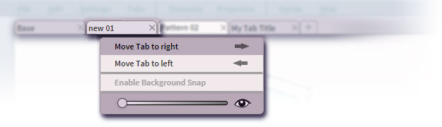
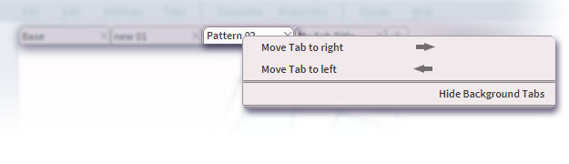
Right click on a pattern tab that currently is in the background reveals additional options:
The arrows allow shifting the tab for- or backwards in their order.
The slider is for background visibility. Only visible tabs can be snapped to!
Enable Background Snap - it toggles the ability to snap to tools in this background tab while working in your active pattern tab.
Right click on the active pattern tab reveals a few less options, replacing background visibility and snap option with:
Hide Background Tabs - it hides all background tabs. The same features exists in the menu bar under 'Tabs'.
*This little slideshow only shows a few examples of input tabs. There are currently 31 different configurations throughout...
The User Input Tab is the one place where each tool and feature allows you to enter values and provide quick and easy access to certain choices, depending on what tool or feature is currently active.
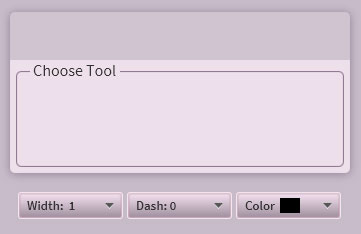
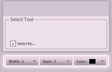
The only somewhat fixed section here are the three pulldown menus along the bottom of it:
Width: choosing the line width
Dash: choosing a dash pattern
Color: choosing the color
These change only for Text...
Size: choosing the font size
Font: choosing the font family
Color: choosing the color
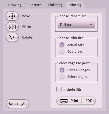
...while activating "Select By" or while on the print tab. More on all that later...
For much of the User Interface there's little unusual to know about the mouse, except once it comes to the "paper" and drafting. Here the mouse buttons together with the keyboard's modifier keys like Shift and Control showcase some exciting virtuosity.
White Rabbit CAD is designed specifically for the creation of clothing patterns and therefore deeply supports important gestures and behaviors, relevant to the drafting of such patterns.
The left (primary) mouse button simply acts like one might expect, allowing you to start actions like creating tools or applying modifications and drag things out while you keep down the button until you let go. Some tools and features also allow you to simply click to where you wish to start some action and then use the User Input Tab to determine the desired result like making a line to specific coordinates or a specific length, but more on all that later.
The right (aka secondary) mouse button , rather than having a separate set of snap toggles, will always SNAP, when snapping is possible and will be aware of what you are doing. Priority is given to end points of tools, while it also snaps to anywhere along tools, be that lines, bezier curves, arcs or circles. Whether you create a new tool or use a modifier such as move, rotate or any other, it will snap and prepare for what comes next, if you choose to add holding a keyboard key. More on that comes right away...
One curious thing to note is that you may start a dragging action with the left mouse button, but then add the right mouse button to snap only the end of the action. Such as starting a line without snapping and only snapping the end of it to some other tool. It's not usual to want that, but nevertheless it's possible. ☺
The middle mouse button is for panning and will always work, regardless of what else you may be doing. Therefore you can, for example, drag out a bezier curve and both pan and zoom to where you need it to go, in case it was outside of the currently visible space. Simple don't let go of the other buttons. This may sound odd at first, but it's stunningly quick to get used to this and take it for granted.
The mouse wheel is for zooming, unless you're on a scrollbar. Use the wheel at any time, just like the middle button. This allows to zoom in or out even while you are in the process of drafting a line or moving any tool or the likes. Again, it's surprisingly uncommon and dangerously easy to get used to.
Sandbox
shows up on larger browser windows.
Sandbox
Here's a little sandbox to try out the mouse...
(on mobile this may not work properly!)
press Left Mouse Button and drag to draw lines
press Right Mouse Button and drag to draw snapping lines
press Middle Mouse Button and drag to pan the canvas
use Mouse Wheel to zoom - or use [ + ] [ - ] keys
hit or hold U to undo
hit or hold Shift+U to redo
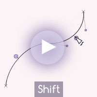
hold Shift as you drag lines to lock compas directions
Only few hotkeys are currently mapped to trigger features. The future appears to belong to tablets and mobile devices, most of which have little use for hotkeys on a keyboard. However, we still consider adding customizable hotkeys at some point. In the meantime...
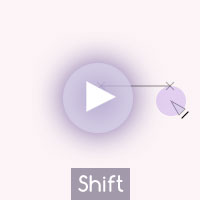
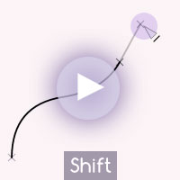
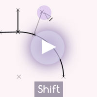
Shift generally locks dragging operations either to compas axis (horizontal, diagonal, vertical) or relative to tangents of tools one might have snapped to such as lines, bezier curves, arcs or circles.
While adjusting Cubic Bezier Curves that are connected, holding Shift and clicking on a curve handle will toggle the handle relationship between the two curves.
Control temporarily activates the Select Mode while holding the Control key.
Control + a will select all tools and finishing tools (Buttons, Grainlines, etc...) on the canvas.
Control + i will invert the selection of tools and finishing tools on the canvas.
Control + x will cut the selected tools and store them on the clipboard.
Control + c will copy the selected tools to the clipboard.
Control + v will paste the tools from the clipboard onto the canvas.
Control + d will duplicate/clone the selected tools.
Control + z will undo.
Control + Shift + z will redo.
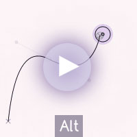
Alt besides standard menu activation, while adjusting Bezier Curve Endpoints it will maintain the curve proportions.
+ and numpad plus will zoom in by a step.
- and numpad minus will zoom out by a step.
Escape will break up or exit out of active features and functions.
Delete will delete selected tools and finishing tools. More on what this can do later...
Arrow Keys will move selected tools by larger steps.
Shift + Arrow Keys will move selected tools by smaller steps.
PageUp will move selected elements up (above) in their order of appearance.
PageDown will move selected elements down (below) in their order of appearance.
Home will move selected elements to the top of the order of appearance.
End will move selected elements to the bottom of the order of appearance.
p toggles Show Endpoints.
...turns out we still do have quite a number of hotkeys. ☺
On paper one would use rulers of various kind, compasses, pens and pencils to draft out patterns. In White Rabbit CAD we replace them all simply with what you wish to create. Be that lines, curves, circles or arcs, everything measures as you make it and you may always adjust each tool numerically to exactly the length, size or angle you wish them to cover. Even text is a tool, allowing you to swiftly add labels or any information where ever you desire.
Additionally there's also a measuring tool, which comes in handy, while each tool already offers instant measurements as you drag them out and tool lengths can be combined by selection, but more on that later...
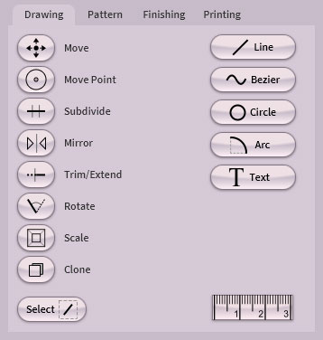
Our objective is to capture the sense of directness that comes from working on paper and let the computer really show its true power to improve the workflow and experience beyond undo and redo. And The Tools are at the very heart of it all:
Changing the line width, the dash pattern or the color of the tool is done with this panel under the User Input Tab:
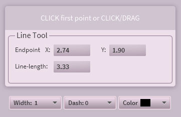
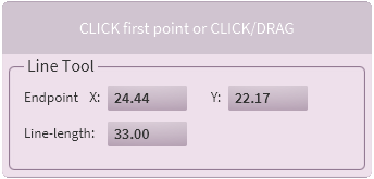
Traditionally to make a line one would use a straight ruler and a pencil and carefully draw a line until a certain length is reached. Our take on it merely skips the worries and lets you drag out a line directly and always freely, but with the option to set a specific length directly afterwards or even snap to existing parts of the construction in virtually all conceivable ways.
The Sandbox gives you a good opportunity to experience a little bit of our line tool as a- literally- tiny emulation in your browser.
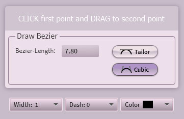
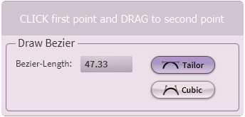
Bezier Curves are the most elegant and simple, yet most complete approach to making curves. There's virtually no kind of curvature you can't make and staggering flexibility within just one single Bezier.
We've created a novel mode in the use of Beziers by introducing the Tailor Bezier. It allows to place the apex of the curve directly to where you want it, rather than having to adjust various handles to hopefully get there. It's conceived specifically for the work on clothing patterns, as virtually everything in White Rabbit CAD, and it makes it very easy and quick to get the right kind of shapes for sections like sleeves, armholes, necklines and the likes. In the follow little video you will also see how you immediately get the measurements of the curves.
►
If more curve segments are desirable, one would likely prefer to use Cubic Beziers, which give you handles toward each end of the curve and a free flow of the curve between them. It's easier to chain such curve segments together.
►
Another unique power of our Bezier implementation enables a change of curve length by automatically adjusting the handles accordingly. This makes it fairly easy to ensure the seam alignment between two patternpieces along curved seams.
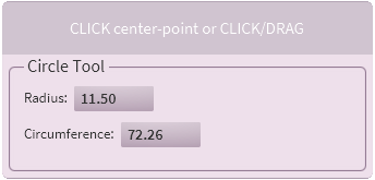
In pattern drafting, circles are mostly just guides for the construction process, but our circles can actually get subdivided like all other tools, too, making them a bit more relevant for the process.
Like with lines, you can alter the radius after you have dragged out a circle, but you may also set the circumference instead.
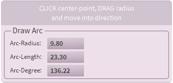
Arcs in White Rabbit CAD can finally be arcs again and won't have to substitude proper curves. However, arcs are still powerful in their own right and can be more than just guides.
Like with circles you start by setting the arc's center first and drag out the arcs radius until you arrive at where you wish the arc to start. After letting go of the mouse button the arc remains active so you may set the end of the arc. You may press and drag to be able to snap to a target for the end point. Afterwards you can also change the arc-radius, arc-length or arc-degree with the numerical input.
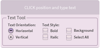
Writing labels and placing measurements is an important feature and we have done our best to make this as convenient and as consistent as possible, integrating text just like any other tool. Of course, this is not a word processor, but even here White Rabbit CAD still has enough to offer to properly label your patterns. Though you can use all standard modifiers like move, rotate and scale, we've packed a few convenience features right into the writing process like moving the text and switching between horizontal and vertical alignment.
►
Use any font you have installed on your system.
Toggle background border around your labels.
Select All to toggle the selection of all text tools.
Flip between horizontal and vertical alignment.
Modify text with all standard modifiers like move, rotate and scale.
Set Color and Opacity.
Changing font size, font family and the color of the text is done with this panel, which replaces the line settings panel:
Another key to White Rabbit CAD's ease of use is that all tools can be edited with the same set of modifiers. This may not sound very miraculous at first and very quickly you will take it for granted as has been our intention, too.
You may wonder about the order of those modifiers. It is designed with the workflow of creating patterns in mind and the visual clarity of the interface. Orientation and intuition are most important to eventually focus entirely on the project at hand and not be troubled by searching for features in the software.
Some of the modifiers only alter the appearance of selected tools, while others will create new tools in various ways like subdividing, mirroring or cloning. More on all this follows...
To start off, we should first look at the Select feature, because it is vital to many of the modifiers. It comes with enough extra options to deserve its own place in the manual.
Once the Select button is activated, you may select tools on the canvas by either using the left mouse button to click on them or dragging a selection box around the tools you wish to select.
If you click on an already selected tool, it will get deselected.
Hold down Shift to ensure to continue selecting.
Double click on a tool will select tools directly connected to it.
Tripple click (yes, indeed) will try to select a whole chain of connected tools, while it may branch off depending on the construction. This is usually useful for selecting continuous frames like around patternpieces or their seam allowances, all of which we will discuss later...
The selection box will by default deselect all before selecting the tools that touch the box. Here, too, holding Shift will not deselect anything and only add to your selection.
If you use the right mouse button to drag a selection box, it will deselect what it touches.
Clicking in open space on the canvas will deselect all tools.
You may also use the hotkeys Control+a to select all or Control+i to invert the selection.
It's well worth mentioning that UNDO and REDO will also work on selections. Despite all best efforts, one cannot prevent the occasional slip up during selection or the desire to investigate steps backwards through the process. The inclusion of the selection process into the undo stream gives a very pleasant sense of security and ease of mind.
Another fantastic way of selecting items is via the "Select By" option. This is a major feature to let you develop your own workflow as you can group tools by appearance such as line width, dash pattern or color. Enable "Select By" and you may choose any setting or combination of settings to select and/or deselect items that fit the parameters.
Once "Select By" is enabled, a white halo shines around the tool property panel.
Once we get to the Patternpiece section and the Pattern Table, additional selection options will be presented and explained as well. We're taking selection very seriously! ☺
Move simply does what it says, allowing you to move all selected items around. Use the right mouse button to snap both the place where you grab hold of the tool you wish to move and it snaps to the tool you wish to move it to.
The User Input Tab offers two parameters, move X and Y, where you may enter exact distances for a move.
Also, independent from the move modifier itself, once you have tools selected, you may always use the cursor- or arrow- keys to move them around. Holding down Shift will switch to finer steps per key hit.
Move Point is a little more complex than just move. While you may just move a single end of a line, for example, or bezier curve handles, you can also select a number of points by clicking them "on" one by one before you start dragging them to a new position. You may also drag a box, much like the selection box, around the points you wish to move.
As with all modifiers, snap works as ever, using either the right mouse button or having the little snap-magnet
toggle turned on.
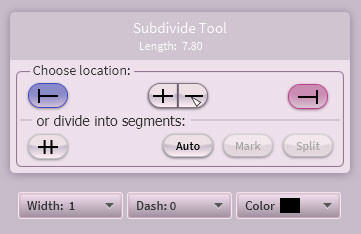
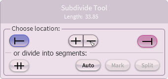
Subdivide is a nearly magical feature you will likely use a lot. Except for text, all tools can be subdivided. It's use even goes beyond just subdivision, but more on that in a moment.
Under the headline of the Input Tab- "Subdivide Tool"- you will see the length of the chosen tool- or tools- giving you some important information right away.
A tool chosen for subdivision will show a blue dot on one end and a red dot on the other. These are represented in the Input Tab by the blue and red toggle buttons. Activate one of them and a numerical input will open up. There you can enter the desired distance at which the tool is meant to be split.
Between the blue and red toggle buttons there are two more buttons . The left button sets the split point into the middle of the chosen tool. The right button allows you to freely chose any number of breaks along the chosen tool.
In the lower you row you'll find the Segment toggle allowing you to input an amount of segments into which the tool shall be subdivided.
Last, but not least, there is the Auto button . Press this and the tool will be split by all other tools that intersect with it. This is the only button that will not activate the Mark and Split buttons, but instantly act.
Once you've made your choice on where to split the tool, the Mark and Split buttons will become active. Choose Split to cut the tool into the respective pieces. Sometime you don't wish to split a tool, but merely leave marks. Mark will make those special marks at the desired locations and they are only there to snap to. You can always delete selected marks or all of them. However, for most of the time you likely will want to split the tool.
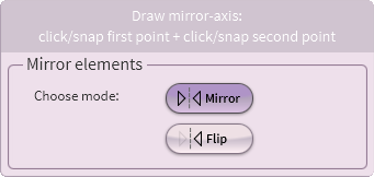
Fairly straight forward, Mirror allows you to mirror selected tools- or items- along a freely drafted axis, which creates mirrored clones. If you choose Flip instead, it will merely flip the tools/items and not create clones. A powerful and useful feature, but there just isn't much more to say about it.
Another new best friend will be the Trim/Extend modifier. It requires no Input Tab and simply allows you to trim and extend a chosen tool or multiple tools to trim or extend to another chosen tool. It sounds so simple, but it's such a vital feature along the way and it somehow is fun to use, too.
Most peculiar is the ability to trim and extend Bezier Curves, though there are limits as to how far you may want to extend them. We've enabled Beziers to extend, but they will maintain their formula, which can lead to some unexpected curves with their own will. Luckily there's always UNDO, thus there's not much to fear. However, it does invite some interesting experimentation and often is most valuable, as you will notice soon.
To Rotate you first set the center for the rotation and drag an axis to where you want to start the rotation from.
You may snap to that location, using the right mouse button or having the little snap magnet
active.
Then you may rotate your selection freely, use Shift to compas lock or again use snapping to snap to your target.
Afterwards you can always go into the Input Tab and alter the rotation amount either by direct distance from origin to a target location or by entering the desired degrees.
Similar to Rotate, start by setting the center and drag out an axis to where you want to start scaling from. Snapping works as always.
After that, scaling begins as you bring the axis to the length you wish to scale to. Here, too, snapping works as always. Holding Shift can be useful in both parts of the process.
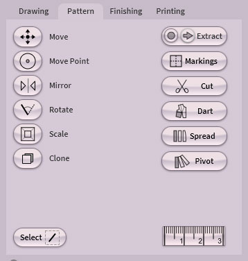
A clothing pattern ultimately consists of patternpieces, which are more than just groups of lines and curves and which want to be modified and edited as a whole. In White Rabbit CAD we've dedicated a whole portion of the software to them alone, giving you a number of features that are common and even essential to the construction of patterns in all stages.
A patternpiece is a closed loop of tools, their resulting, combined surface and all markings the piece might need, but more on the markings later.
Possibly the biggest challenge here is not to mistake our little white rabbit for an illustration tool, because it can look rather playful. Yet, each patternpiece contains and holds a great deal of information besides all the tools it is made of. This makes it extremely fast for pattern construction, but rather heavy for freeform art. That being said, it's quite tempting to explore the latter at times. We still recommend sticking to CAD purposes! ☺
Extract is one of the more mysterious features, as it has a rather complex duty to perform. Depending on what you ask it to do, it may have to analyze the whole content inside the pattern tab and reform all tools properly for it to "see" what it needs to do. This is far from trivial, but the result is quite magical to those, who understand as well as those, who wouldn't know the depth of extract's powers.
Extract will do its best to find closed shapes, but will only give you a result when it has found one. There are certain tolerances, but it does rely on your precision to be sure that it won't fail or mislead you.
There are three modi or options you can activate via the input tab:
Autocut will split tools for the resulting patternpiece in order to create closed shapes.
Connect will try to connect tools that are not entirely connected, given a small tolerance.
Include Markings will add all tools that are on the inside of the extraction area and even cut those, which cross through it.
The Extract Button itself is the most exotic of all the buttons, having a slightly more complex behavior.
This button contains three buttons within itself:
Extract the largest portion of the button activates the Extract Input Tab.
Record the little red recording button will start the extract recording.
Store/Stop the little green arrow stops the recording and will store what you have extracted as new patternpiece.
Markings are the extra tools that you may want on a patternpiece surface, but that do not describe its outline.
For example, you may want to keep other construction lines that help with the editing of the piece like placing darts and the likes.
While you can automatically inlude Markings during Extract, you may want to add more markings later or remove unnecessary lines.
Seam Allowances actually add their lines to the patternpiece as markings, allowing you to fully edit them after their creation just like any other tools. This includes removing any of their segments or even adding new tools to them. You would do the latter via Markings Add or Remove.
If you simply draw new tools over your patternpiece, it will not know, if you want those to belong to the patternpiece automatically. For that you will want to Add those new tools as Markings. However, if you wish to delete certain markings, you can also just select and delete them.
To add or remove markings:
select the patternpiece you wish to modify
click on Markings
on your pattern tab you now may select the tools you wish to add or remove
choose Add to add the selected tools to your patternpiece
or choose Remove to remove the selected tools from your patternpiece
Cut allows you to virtually slice through a patternpiece, creating one or more new patternpieces out of the resulting segments. You have the option to delete the original patternpiece, while this suggests you are very unafraid, because that cannot be undone!
After turning Cut off again, the last piece will automatically be selected, allowing you to immediately edit it to your liking, like moving or rotating it. This is quite convenient, if you choose to work that way.
Dart here is short for Dart Transfer, providing several ways to alter the placement of darts:
After activating Dart you select the patternpiece you want to edit. Then you pick the pivot point of the dart. Then you choose the fixed leg of the dart. Then you choose the closing leg, which later then will rotate to close the original dart.
Now you may review your choices and potentially alter the settings in the input tab.
Once the settings are to your liking, you can drag your transfer target axis to where you wish it to go. The target can be freely placed or using the snap feature
.
Transfer by percentage
►
►
►
Close to a desired measure
►
Close by a desired measure
►
Open destination dart by a desired measure
If you choose to open the new dart by a desired distance, you have to snap the end of the transfer axis exactly to where it should go, because the length of this axis will be used to calculate the required rotation for the desired opening distance.
Slash and Spread allows you to comfortably expand pieces of your pattern, be that to add volume, extend length, insert pleats or even box-pleats, just to mention a few of the many good reasons to use and enjoy this feature.
The various options are:
Simple - slashes patternpiece at chosen lines and spreads the pieces by the desire gap distance.
Pleats - automatically completes the added gaps in the chosen direction.
Box Pleats - automatically completes the added gaps.
Slash and Pivot is much like Slash and Spread. Instead of moving the slices apart, here they get rotated apart. The pivot for each slice is at a chosen end for all slices. You may even choose to add a spread to the pivot end, making it a possible combination of slash and pivot and spread.
The beginning procedure is the same as before. After activating the feature, you choose the patternpiece you wish to edit, followed by the picking the lines by which the patternpiece shall be slashed.
Simple - slashes patternpiece at chosen lines and pivots the pieces by the desire distance.
Pleats - automatically completes the pleating in the chosen direction.
Box Pleats - automatically completes the box pleating.
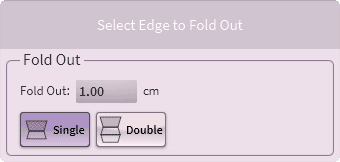
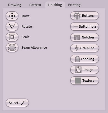
True Dart, Fold Out and Seam Allowance, along with all other tools to finish your patternpiece can be found here under Finishing.
That also means you must have already some patternpieces to apply to most of the tools and features you find here.
Here you may add buttons, buttonholes, notches, grainlines, patternpiece labeling, images and you may set a texture for the filled area of a patternpiece, if you wished to include those in the print, or simply enjoy the extra orientation.
Seam Allowances will end up as markings around your patternpiece, but more on all details further down...
It's highly likely that we will add additinal finishing features in one of the coming updates, but this is already a powerful and wholesome set of tools.
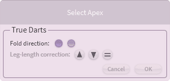
True Dart will apply proper caps over chosen darts and will true both darts and seams with or without adding a cap.
Fold direction - Choose into which direction you wish the dart to be folded.
You may choose your direction in the input area or directly in the drawing area.
Leg length correction - will true dart legs with a choice of shorter, longer or average leg length.
In order to properly close a dart, both legs have to have the same length. Here you have three choices to automatically correct the legs. It will also try to properly deal with the seams on the edges of the dart.
True Dart is one of the few finishing features, which will work on pure line constructions as well as on patternpieces. After having selected a dart you may choose to only correct the leg length of darts without adding a cap by not choosing a fold direction and finishing the action by either hitting "OK" or clicking anywhere else on the drawing area. As soon as you have chosen a fold direction, finishing True Dart will add a cap over the dart accordingly.
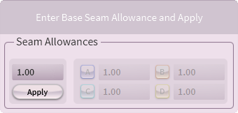
Adding Seam Allowances is as easy as selecting a patternpiece, setting a distance value and hitting apply.
If there is only one patternpiece on the current sheet, the input field's "Apply" button will immediately be active. If there are more than one patternpiece on the sheet and none is selected, you will first have to click on the patternpiece you wish to add seam allowances to. If your currently selected patternpiece already has seam allowances applied in this session, the "Apply" button will turn into a "Clear" button, which will then remove the existing seam allowances first. But also the "A, B, C and D" buttons will be active. More on those follows...
Apply/Clear - hit to apply or clear seam allowances (of this session).
When you apply seam allowances, they will have the currently chosen width, dash and color settings. It is useful to develop your own conventions, regarding these settings, as it will help with both orientation and handling later on!
A, B, C, D - variables for different seam allowance distances.
Once you activate A, B, C or D variables, you will be able to go to the drawing area and select edges to become tied to the active variable. You can alter the value for each variable at any time and all chosen edges will change accordingly. A value of 0.0 will turn off the chosen edge, such as for fold edges. We recommend setting those 0.0 edges as the very last adjustment!
Seam Allowances will turn into "Markings" of a patternpiece and currently will be saved with the project as such. After loading a project back in, they will no longer be recognized as Seam Allowances. If you wish to alter them, you may have to select and remove them first manually, but we will likely make that more comfortable in the future. If you have developed your own settings conventions, Select By will make such selections quick and easy.
Initially it was inspired by the movie "The Matrix", where following the White Rabbit would lead to the next step of awakening and therefore control. Few things represent an awakening like the power to realize a creative idea and then carry- or wear- it into the real world like creating your own clothing. But then we also thought about an old Chinese legend of the White Rabbit, named Yutu, on the moon. He once was asked to come down to earth and heal a region, where people fell ill. He did so and only asked for one thing in return: Clothing for men and women that he could wear while he was roaming the earth in human form to heal the people. How fitting it would be to dedicate a pivotal tool for the process to the White Rabbit.
Last, but not least: You are the magician, and this is merely your White Rabbit! ☺


 and red
  toggle buttons. Activate one of them and a numerical input will open up. There you can enter the desired distance at which the tool is meant to be split.
 . The left button
  allowing you to input an amount of segments into which the tool shall be subdivided.
 . Press this and the tool will be split by all other tools that intersect with it. This is the only button that will not activate the Mark and Split buttons, but instantly act.
 and Split
  buttons will become active. Choose Split